
iSpindel Project – Post 2
Whenever it comes time that you want to build a DIY product, you really must understand the bill of materials first. For the iSpindel, it just was not very straight forward. There’s nobody really explaining what everything is and how it’s all used. The documentation for this just doesn’t make it all very clear. So I’ll do my best explain what each electronic part is, what it does, and where you can find it.
The brains of the whole operation is the ESP8266 chip. This tiny little chip packs of a lot of cool stuff in it. But unless you’re an electrical engineer, you don’t want to go out and buy this chip and build a circuit around it. You want all of that stuff done for you. The German folks who first put together the iSpindel were fans of the Wemos D1 Mini. The Wemos D1 Mini is a cool little single-board micro-controller that has all of the various things you need to interact with the ESP8266 chip.
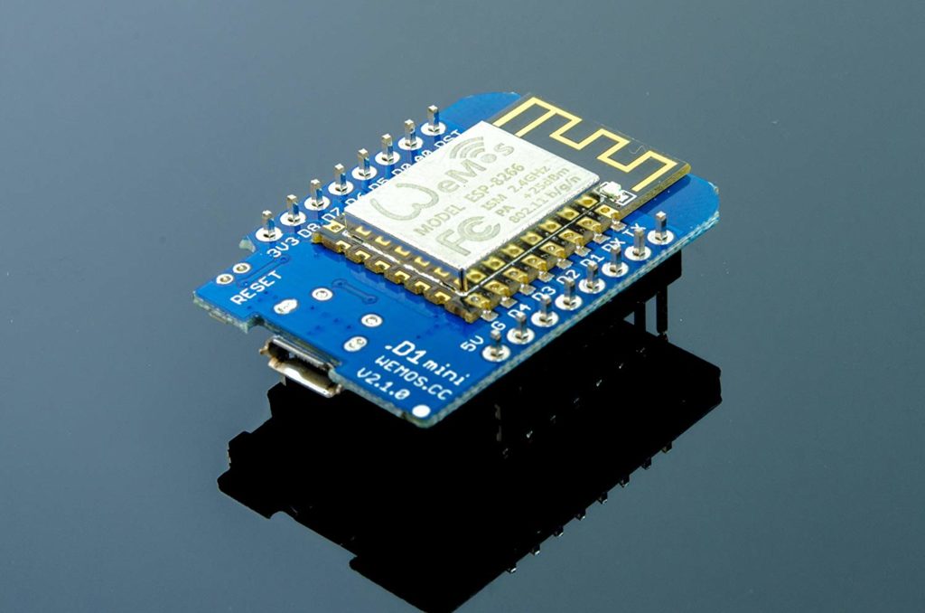
But the D1 Mini doesn’t have the necessary sensors to give you the information you need to take all of your measurements. For that, you need to add a temperature sensor and a gyroscope.
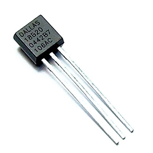
For the temperature sensor, that’s easy. There’s a very popular temperature sensor called the DS18B20. This little guy is super cheap and readily available anywhere.
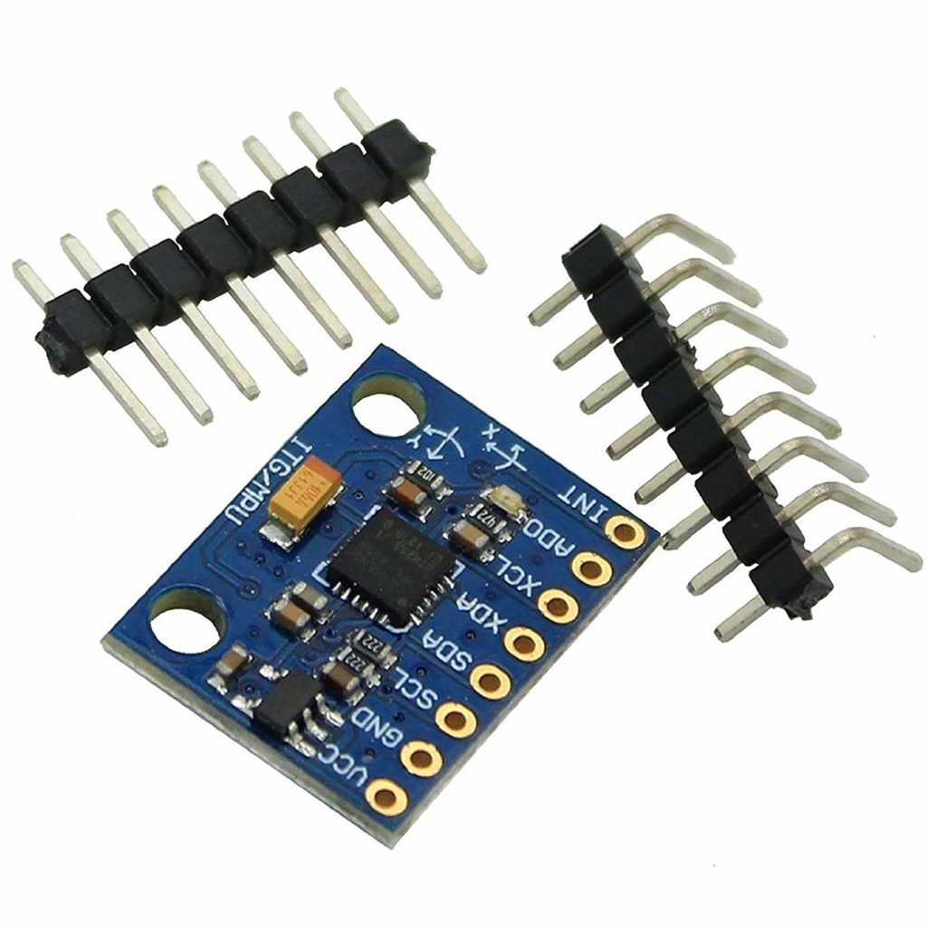
For the gyroscope our friends in Germany are recommending the MPU-6050 which is a very popular chip. But much like the ESP8266, you don’t want to buy just the chip. You want to buy a daughter board (often called a shield) that has all of the various control circuitry built into it. The GY-521 is a great daughter board for this purpose.
Once you’ve got those 3 main pieces of silicon (micro-controller, temp sensor, gyro), it’s time to power these bad boys. That’s where your Panasonic 18650 battery comes in. This is a hefty, lithium-ion rechargeable battery, packing 3400 mAh into one tiny package.
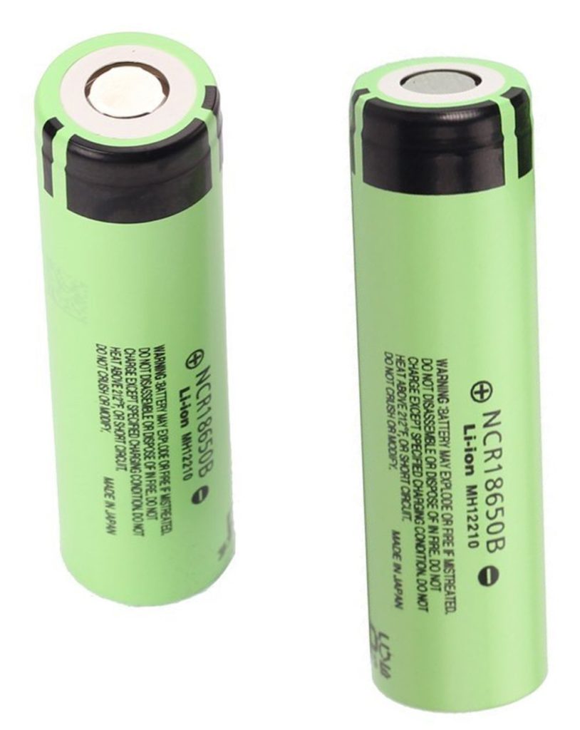
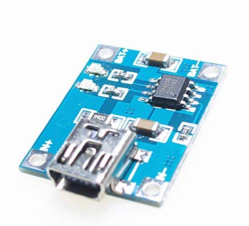
In order to control this battery, and be able to recharge it, you will want to use some kind of lithium-ion battery controller. Again, our German friends to the rescue. They recommend the TP4056 controller. This is a very popular DIY battery controller module that plays nicely with the Panasonic 18650 battery and the Wemos D1 Mini.
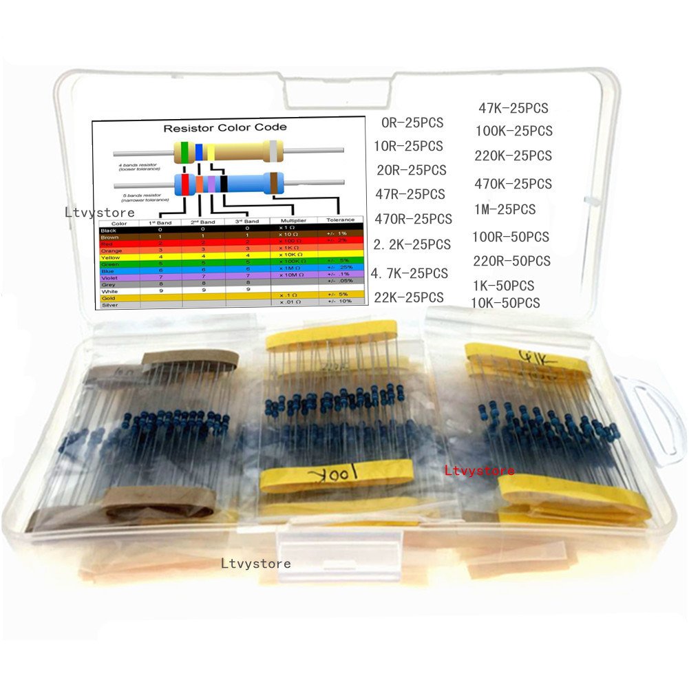
So now we have our silicon, we have our power, it’s time to wire all of these things together and give them an on/off switch. In order to do that properly, you’re going to want a few other electronic components. A solderable breadboard, an on/off switch, a 470 ohm resistor, a 4.7k ohm resistor, and a 230k ohm resistor. If you’re not familiar with resistors, ohm is the unit of measurement and “k” means “thousand”. So when you say 4.7k what you really mean is 4,700. When you say 230k what you really mean is 230,000 and so on.
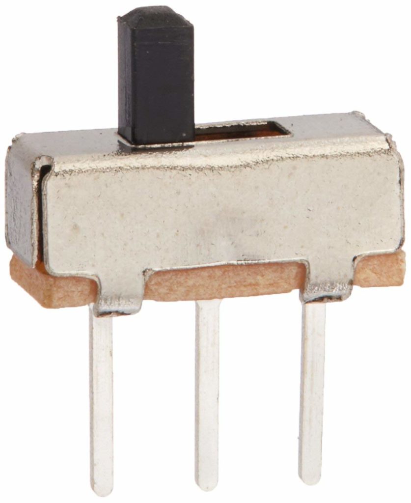
There are all kinds of switches out there. They’re all dirt cheap and they all usually work really well. That being said, because they’re so dirt cheap, it’s nearly impossible to find just 1 of these at a reasonable price outside of a large electronics distributor’s website. So if you order these from the link I recommend, you’re going to end up with 50 of these. Better get creative with the other 49 of them.
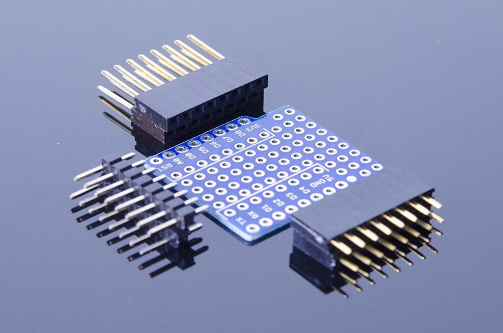
There are a bunch of various solderable breadboards out there, but you’ll probably want one that is designed for the Wemos D1 Mini. It’ll just make your life a little easier when you solder all of these things together.
For the resistors, you could buy each of these resistors individually, but usually you’ll spend just as much, if not more, for shipping these things than if you just bought a kit with all kinds of resistors, so that’s what I’m recommending in my bill of materials.
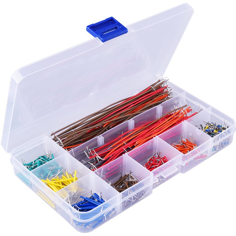
Finally, you’ll also need a few various sized jumper wires. If you’re really desperate, you can just cut the leads off of some of the resistors you’re not using to make your own jumper wires, but in case you can afford another $10 kit, I’m recommending a popular kit from Amazon.
Once you’ve got all of your electronic parts, you can begin your assembly and write the code to the ESP8266 chip. More details on how to do all of that in an upcoming post, but for now, reference these couples of pages from the community.
I hope you found this information helpful. And finally without any further ado, here is your bill of materials, with all items available on Amazon.
Bill of Materials
- Micro-Controller (Wemos D1 Mini) – https://www.amazon.com/dp/B01MDRVUQU/
- Temperature Sensor (DS18B20) – https://www.amazon.com/dp/B077NYFYZS/
- Gyroscope (MPU-6050) – https://www.amazon.com/gp/product/B008BOPN40/
- Battery (Panasonic 18650) – https://www.amazon.com/gp/product/B01C4GFVN8/
- Battery Controller (TP4056) – https://www.amazon.com/gp/product/B00HJNX0DU/
- Switch – https://www.amazon.com/dp/B007QAJUUS/
- Wemos Compatible Breadboard – https://www.amazon.com/gp/product/B07G3227MD/
- Resistors – https://www.amazon.com/dp/B07CBV473M/
- Jumper Wires – https://www.amazon.com/dp/B07CJYSL2T/
Nice article. Any reason you don’t make the links clickable?
Oh good catch! I’ll fix that.
All fixed up. Thanks again for pointing that out.
I seriously think we should look into using the MPU-9250/6500 (https://www.amazon.com/gp/product/B075H8X7H2/ref=ox_sc_act_title_2?smid=A1N6DLY3NQK2VM&psc=1) or L3GD20H (https://www.amazon.com/gp/product/B07HBSJCFP/ref=ox_sc_saved_title_5?smid=A26ATEC08S9EFM&psc=1) break-out boards which include a temperature sensor on board. This way we can remove one extra component with the DS18B20 temp sensor and additional associated components. Also, they have a WEMOS D1 mini PCB with 18650 holder integrated (https://www.amazon.com/gp/product/B01I1J0Z7Y/ref=ox_sc_act_title_1?smid=A30QSGOJR8LMXA&psc=1), which removes the need to build a custom PCB to integrate a 18650 battery and charging/controller components. Also, Amazon no longer sells the Panasonic 18650 battery, but, you can get it here https://www.batteryjunction.com/panasonic-ncr18650b-3400.html
Yeah I saw this literally minutes after posting this whole thing. Definitely think it’s worth pursuing. But my inner nerd wants me to do it the hard way!
That’s what my parents always said I’d do 😉
Many thanks for taking the time to post this artical. it has some great images and very clear explanations of the project and components. I have recently built one of these and after a little trial and error I have managed to get it in a brew and I am monitoring happily on Brewfather.
I would be really keen to see your build if/when you get around to it because if it of the same quality as this article it will be invaluable for the many home brewers struggling to get to grips with making the device.
Thanks Joe. I really need to get on it. I’ve gone ahead and built some prototypes that work but I want it to be more refined. I’ll try to post an update soon.
Hi, thanks for posting this 🙂 I followed your parts list and have got everything ready to go, however, the breadboard you posted is different from the ones on the instructions (not as many holes? Not only that i’m finding it slightly confusing, not 100% whether points are soldered or just look it, and their two pictures of the green board aren’t of the same board, so i’m wondering, do you have a picture or two of how you soldered it all together using the blue breadboard?
Many thanks
Hi Dan. Sorry for the super late response (over a year later). I recommend you check out Open Source Distilling’s project related to this. He’s done an awesome job. https://www.opensourcedistilling.com/ispindel/
-Chris