

Silkscreen
Silkscreen has long been used on circuit boards to guide the assembler to know what components go where, as well as to show users details about the board such as where power and IO pins can be found. It’s a small detail that is all too often considered less important than other details of a circuit board design, but it really shouldn’t be.
When a manufacturer is getting ready to assemble your circuit board there will be a lot of details they need to pay attention to. They’ll need to make sure all of the locations that should be populated actually are populated, as well as making sure that any locations that have been marked as DNP (Do Not Populate) are indeed NOT populated. They’ll need to confirm that polarized components such as IC’s and LED’s are being populated the correct way so that they function properly. If there is a problem, they’ll need to quickly identify the location and work out the details of the problem. Silkscreen will help with all of this.
Cozy Silkscreen Parameters
When setting up the parameters of your EDA tool’s silkscreen text, I recommend the following “cozy parameters”. These are not minimums by any means, but if you have the room for it, these are good middle-of-the-road parameters that a PCB fab can easily print and an assembly shop can easily read while also leaving enough room on the rest of your board for your layout.
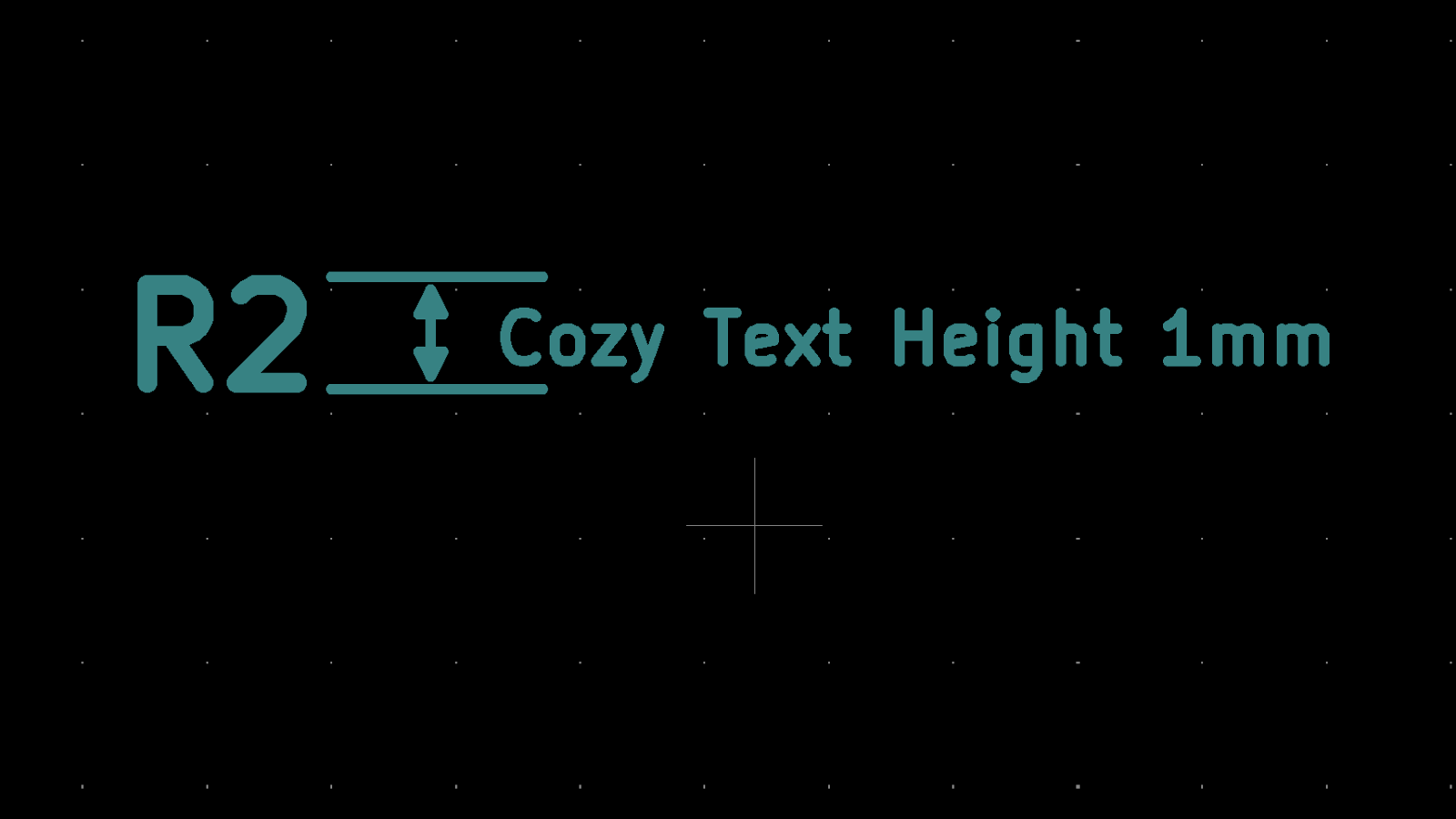
- Text Height: 1mm
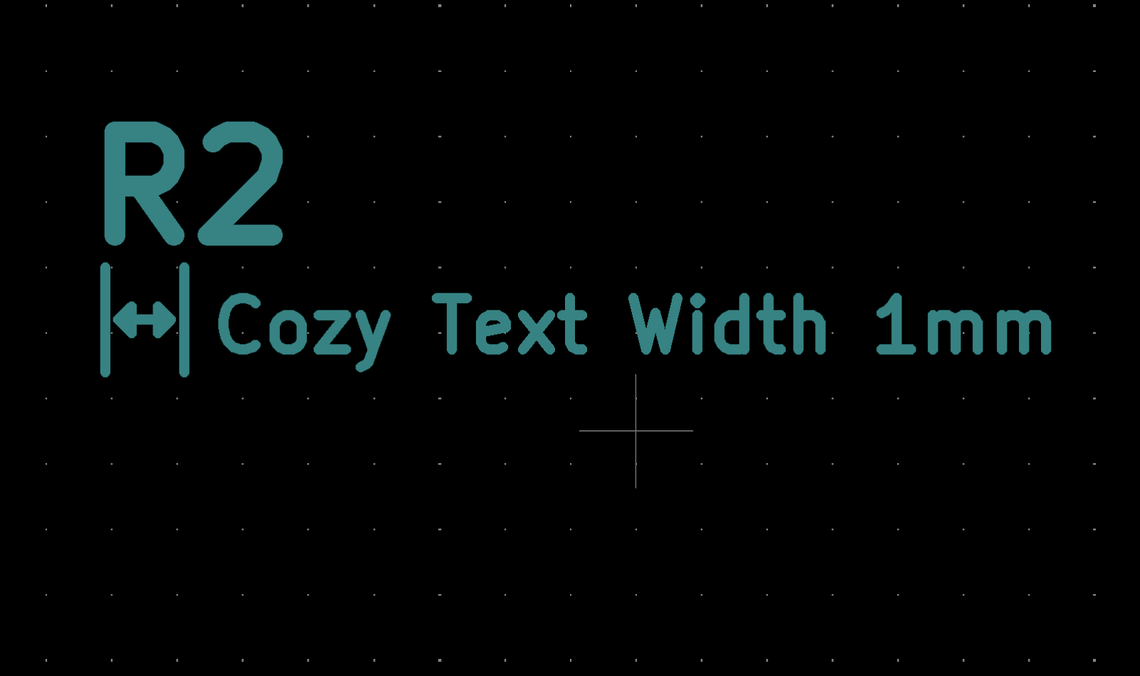
- Text Width: 1mm
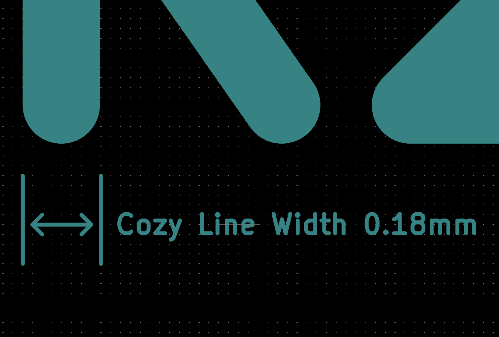
- Line Thickness: 0.18mm
Visibility
Whenever possible, try to keep the relative reference designators for components visible, even after the components get populated. Make sure that the silkscreen doesn’t get drawn across any open vias or thru-holes. And since silkscreen is usually only printed on top of soldermask, it would be a good idea to keep the silkscreen away from any exposed copper pads. If the silkscreen is too close to the soldermask this will be removed, often called “clipping”. In order to avoid silkscreen clipping, make sure no silkscreen is within about 0.1mm of the edge of the soldermask opening.
Polarity Indicators
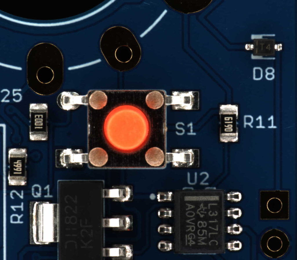
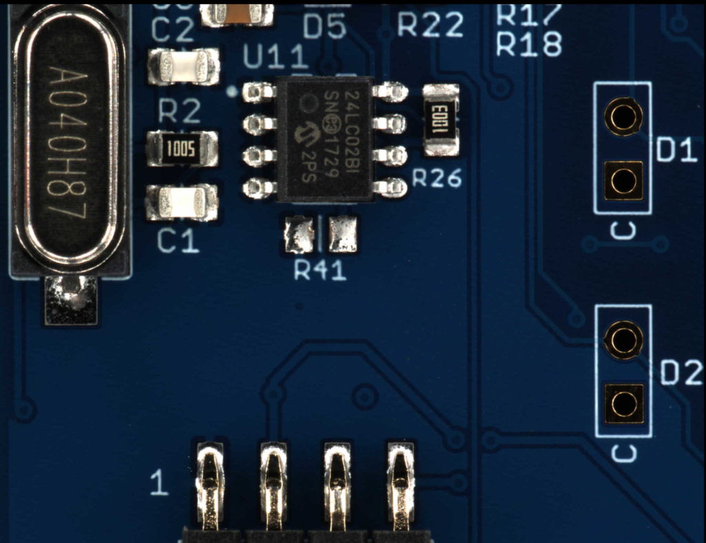
Polarity is something that every assembler is concerned about. Silkscreen is usually the first thing an assembler looks for to define the polarity of a component. Having that silkscreen remain visible even after the components are populated is a great way of confirming that everything was done correctly.
Some examples of how to make sure the polarity of components is obvious would be to put a dot of silkscreen near the pin 1 of an IC, put a numeral 1 near the pin 1 of a connector, and put a C near the cathode pin of an LED. There are plenty of other methods, but these are some of the more popular ones.
Taking the time to make sure your silkscreen is printable, visible, and legible will save you countless headaches and ultimately result in higher yields, quicker lead times, and less phone calls!
This article is part of an ongoing series of articles that will ultimately end up becoming a book I’m calling “Your Manufacturer Is Stupid”. Click this link to see more articles just like this one.
Hey there Chris,
Any progress reports on that book of yours? Very interested in those tips and tricks teased at the end of the stupid fabber presentation 🙂
Nothing yet Bruce. Right now it just lives as a dream. Some day!